Animated Experiment:
Introduction
A tension test is commonly used for determining the quasi-static properties of a material type. Results of tension tests are tabulated in handbooks and, through the use of failure theories, these data can be used to predict failure of parts subjected to more generalized stress states. Theoretically, this is a good test because of the apparent simplicity with which it can be performed and because the uniaxial loading condition results in a uniform stress distribution across the cross section of the test specimen.
Principle
When a prismatic bar is subjected to two equal and opposite forces along the bar axis, a change of interaction force among various parts of the bar is introduced. This change of interaction force is referred to as internal force. In terms of deformation, tensile loads cause the bar to extend longitudinally (axially) and contract transversely. Prior to the eventual breakage, bar deformation can be classified into four distinct stages, i.e. elastic, yielding, hardening and necking. The latter three are collectively termed as inelastic deformation.
Objective
- Identify the elastic, plastic and strength properties of a testing specimen
- Understand the stress-strain curve of typical ductile materials
- Analyze the cold-work hardening phenomenon and its influence on the mechanical behavior of ductile materials
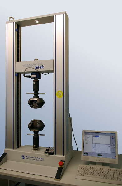
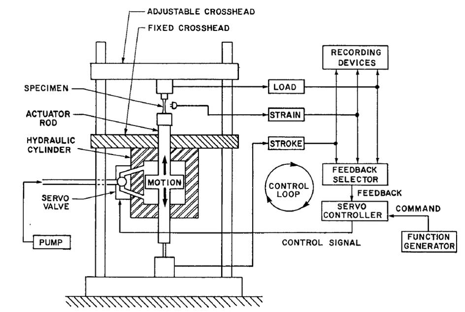
Apparatus
- Universal Testing Machine
- Specimen
Experimental Procedure
- Select appropriate specimen, typically low carbon steel bars
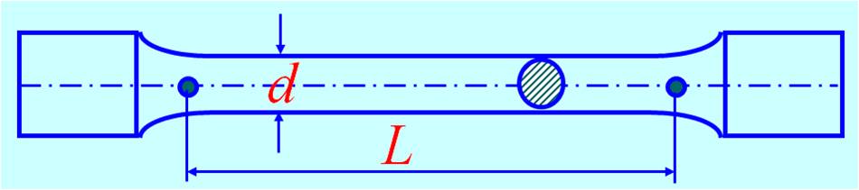
- Measure the transverse dimension with the help of a vernier caliper. For each specimen, measure at least three cross sections and take their average values.
- Determine and mark gauge length, L = 5 d, 10 d for circular cross section; L = 5.65√A, 11.3√A for square cross section
- Make the universal testing machine and associated software ready.
- Grip the specimen between the two cross head jaws of the machine.
- Start the loading process and carefully observe the on-screen stress-strain curve. At a point during the hardening stage, unload the specimen near to zero tensile force and reload the specimen until the specimen breaks.
- Assemble the two broke halves of the specimen and subsequently measure the marked gauge length and the transverse dimension at the most necked section.
Quiz
- What material have you tested? How many percent is its carbon content?
- In what region of a stress vs. strain curve do you find Young’s Modulus?
- Why do you think we remove the extensometer after yielding occurs?
- Determine the proportional limit, elastic limit, yield stress, ultimate stress and fracture stress from the stress-strain curve.
- In reference to its initial dimensions, calculate the relative elongation of gauge length and relative contraction of the most necked section for the broke specimen.
- From the Young’s modulus you have just calculated, determine the elastic and plastic strain components for the unloading point you selected in the hardening stage of the stress strain graph.
- Plot your stress strain curve on a grid paper and determine the modulus of resilience and modulus of toughness for the testing material.
- What is the difference between nominal stress and true stress?
- How shall we evaluate the ductility of a material?
Further Reading
- Universal Testing Machine (http://en.wikipedia.org/wiki/Universal_testing_machine)
- Tensile Testing by Instron (http://www.instron.in/wa/applications/test_types/tension/default.aspx)
- Hooke’s Law (http://en.wikipedia.org/wiki/Hooke%27s_law)
- Yielding (http://en.wikipedia.org/wiki/Yield_stress)
- Young’s Modulus (http://en.wikipedia.org/wiki/Young%27s_modulus)
- Ultimate Tensile Strength (http://en.wikipedia.org/wiki/Tensile_strength)
- Stress Strain Curve (http://en.wikipedia.org/wiki/Stress-strain_curve)
- Tensile Structure (http://en.wikipedia.org/wiki/Tensile_structure)