Animated Experiment:
Introduction
Whenever a structural member is designed, it is necessary that it satisfies specific strength, deflection and stability requirements. Typically strength is used to determine failure, while assuming that the member will always be in static equilibrium. However, when certain structural members are subjected to compressive loads, they may either fail due to the compressive stress exceeding the yield strength or they may fail due to lateral deflection. In the latter case, the structural member experiences a sudden change in its configuration. Further load will cause significant and somewhat unpredictable deformations, possibly leading to complete loss of the member's load-carrying capacity. If the deformations that follow buckling are not catastrophic the member will continue to carry the load that caused it to buckle. If the buckled member is part of a larger assemblage of components such as a building, any load applied to the structure beyond that which caused the member to buckle will be redistributed within the structure.
Principle
Suppose we are to design a column of length L to support a given load P. The column will be pin-connected at both ends and we assume that P is a centric axial load. If the cross- sectional stress on a transverse section is less than the allowable stress for the material used, and if the deformation falls within the given specifications, we might conclude that the column has been properly designed. However, it may happen that, as the load is applied, the column will buckle; instead of remaining straight, it will suddenly become sharply curved. Clearly, a column that buckles under the load it is to support is not properly designed.
An ideal column that is pinned at both ends and subjected to a centric compressive load can be modeled mathematically using the equation of the elastic curve
Young’s Modulus×Moment of Inertia×Elastic Curve Curvature = - Bending Moment.
The above differential equation can be easily solved for the deflection. Given the boundary conditions that the deflection remains zero at both ends, a non-trivial solution of the deflection yields
The Critical Load = n^2×π^2×EI/L^2,
where EI is the bending rigidity, L is the column length, and n is an integer. The smallest value of the critical load is obtained when n=1. Note that this critical load is independent of the strength of the material, but rather depends on the column dimensions and material stiffness. Note also that load-carrying ability increases as the moment of inertia increases, as elastic modulus increases but at length decreases. Thus, fat columns made of stiff material will have very low tendency to buckle. A key to understanding buckling is to create a design whereby the required design load is always much less than the theoretical buckling loads.
Objective
- Understand the buckling failure phenomenon of a slender column.
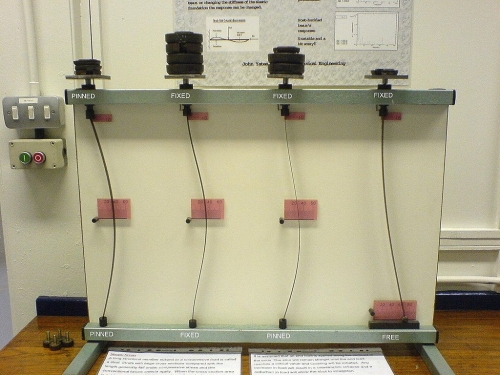
- Determine the critical buckling loads of a slender column pinned at both ends. To achieve failure modes higher than one, constraints at certain cross sections need to be applied to prevent the column from deflecting laterally at those positions, as illustrated in the animated experiment.
- Investigate how the boundary conditions affect the critical load of a slender column by changing the fixture at column ends.
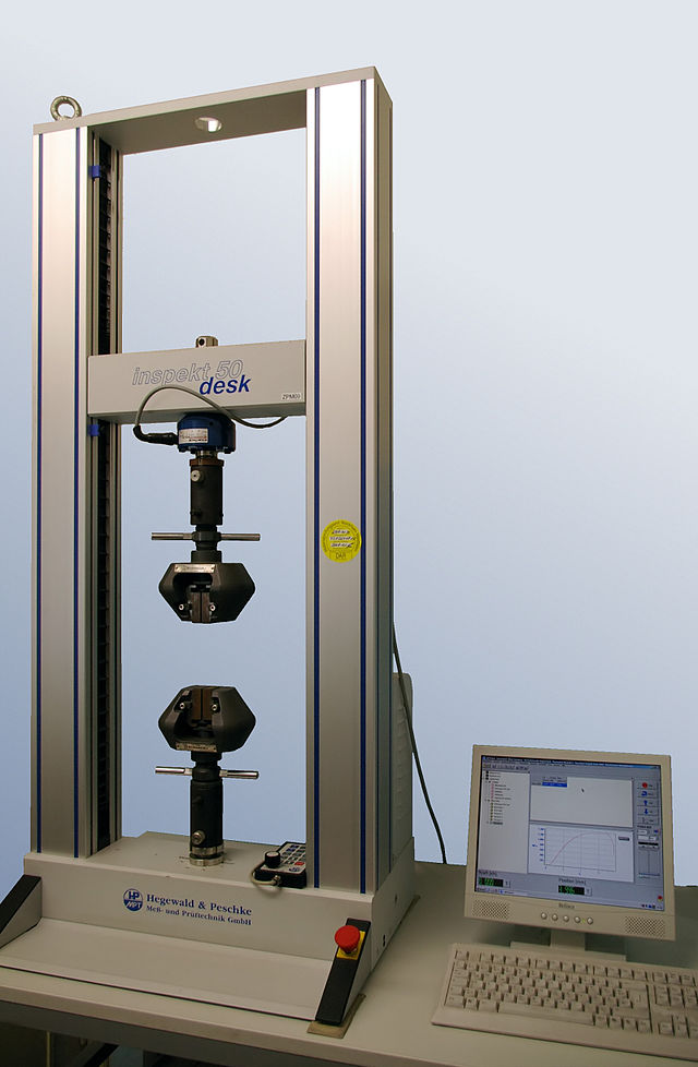
Apparatus
- Universal Testing Machine or Customized Testers
- Slender Columns of Chosen Materials
Procedure
- Select testing specimen and determine its longitudinal and transverse dimension and the material stiffness (Young’s modulus).
- Determine the boundary conditions for the slender column and design appropriate fixture.
- To achieve high order buckling modes, place stoppers near appropriate transverse section to prevent the column from deflecting at those positions.
- From the Euler’s formulae, estimate the critical buckling loads for individual buckling modes and determine the number of load increments.
- Make the universal testing machine or a customized tester ready.
- Mount the specimen.
- Start the loading process and carefully watch for the deformation behavior of the specimen.
- Care should be used when the desired buckling mode is approached and note down the corresponding compressive load. Compare this critical load with that predicted from the Euler’s formulae. Evaluate the accuracy of the effective length coefficient designed for different boundary conditions as stated in a typical textbook.
- Restore and clean up the experimental field.
Quiz
- Why do slender columns buckle instead of yield?
- For a short column, yielding failure takes control. On the contrary, buckling failure dominates in slender columns. Is this statement correct: Euler’s formula is applicable only when its predicted critical stress is less than or equal to the proportional limit of the column material?
- How can we evaluate the safety of a column subjected to compressive loads when the critical stress predicted from Euler’s formulae is greater than the proportional limit, or even higher than the yield stress?
- The original Euler’s formula was developed based a slender column with both ends pinned. How can this formula be extended to slender columns with different boundary conditions?
Further Reading
- Compression Test at Instron: http://www.instron.in/wa/applications/test_types/compression.aspx
- Buckling: http://en.wikipedia.org/wiki/Buckling
- Instability: http://en.wikipedia.org/wiki/Instability