Animated Experiment:
Introduction
Prismatic components, i.e. bolts, pins and rivets, are commonly used in mechanical and civil devices as connectors to prevent the various parts of a structure from falling apart. Very often, these connectors are the weakest parts of a structure. The principal damage of connectors that can be observed is called shear failure in which the connector fails through one of its cross sections. It should be noted that the shear failure of connectors is different from not only the tensile failure but also the shear failure that is observed in a tensile or torsional test. The shear failure of connectors is a special type of damages that is very analogues to the transverse cutting of connectors by a scissor (see the animated shear test for examples).
Principle
The internal forces and the corresponding stresses discussed in a tensile test were normal to the section considered. A very different type of stress is obtained when two equal and opposite but slightly shifted transverse forces are applied to a member. Passing a section that lies in between the application scope of the two forces, we conclude that for static equilibrium internal forces must exist in the plane of the section, and that their resultant is equal to the applied transverse loads. These elementary internal forces are called shear force and they are the cause resulting in the shear failure of the bolt provided that the external transverse loads are large enough.
If there is only one pair of external transverse loads applied on the bolt, the bolt is only subjected to a single shear, like the bolt in the left figure. However, either bolt in the right figure is subjected to two pairs of transverse loads originated from the structural element and two covers. This type of loading configuration is called double shear.
| 
|
To simplify the analysis, an average shear stress, calculated by dividing the shear resultant by the area of the bolt cross section, is often used to evaluate the safety of the bolt. This approximation is of course not consistent with the actual distribution of shear stress on the bolt cross section. From the shear analysis of a beam we learned that the profile of actual shear is parabolic, i.e. zero at both edges and maximum on the centroidal axis. In addition, as a convention no additional types of deformation are considered in the shear failure of connectors. This approximation again deviates from the reality since slight bending is often, if not always, unavoidable. The animated shear test shows an idealized (no bending) double shear failure of a pin.
Objective
- Differentiate single shear and double shear.
- Understand how is the average shear stress determined for both single shear and double shear.
- To conduct shear test on specimens subjected to double shear.
Apparatus
- Universal testing machine (see tensile test for more information)
- Shear test attachment and fixture
- Specimens of a few different materials (brittle and ductile metals, wood, concrete … )
Procedure
- Select appropriate specimen, i.e. brittle or ductile metals, wood, concrete or other materials
- Measure the transverse dimension with the help of a vernier caliper. For each specimen, measure at least three times close to the cross sections that are about to be sheared and take their average values.
- Make the universal testing machine and shear test fixture ready.
- Determine the maximum load and load increments from the ultimate strength and dimension of the chosen specimen and prepare the associated software in accordance.
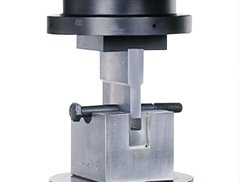
- Mount the specimen in the test fixture.
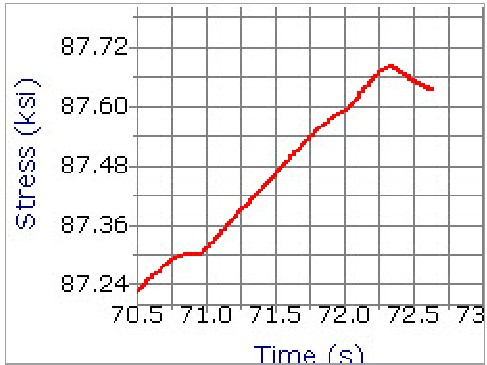
- Start the loading process and carefully observe the damage status of the specimen until it completely shears.
- Translate the test attachment and fixture to a safe position and remove the specimen.
- Examine the special for bending deformation, if any.
- Repeat the experiment with additional specimens if necessary or restore the test device and field to complete the experiment.
Quiz
- What is the difference between a single shear and double shear?
- How to determine the shear resultant in single shear and double shear?
- What is the deference between the shear failure of a connector and that of a tensile/torsional specimen?
- How can the shear strength of a connector be determined?
- Why does bulging (due to bending) occur in a shear test?
- How shall we analyze the exact shear stress distribution on a shear section?
Further Reading
- Double Shear Test of Fasteners at Instron: http://www.instron.cn/wa/solutions/NASM_1312_13_Fastener_Double_Shear.aspx
- Direct Shear Test at Aimil: http://www.aimil.com/Products.aspx?Product_Id=416
- Shear Strength: http://en.wikipedia.org/wiki/Shear_strength
- Shear Modulus: http://en.wikipedia.org/wiki/Shear_modulus
- Shear Strain: http://en.wikipedia.org/wiki/Deformation_%28mechanics%29#Shear_strain