Animated Experiment:

Introduction
Bending is a major concept used in the design of many machine and structural components, such as beams and girders. In Applied Mechanics, bending (also known as flexure) characterizes the behavior of a slender structural element subjected to an external load applied perpendicularly to a longitudinal axis of the element. When the length is considerably longer than the width and the thickness, the element is called a beam.
Bending test provides a convenient method for characterizing the strength of beams and girders of different sizes ranging from concrete specimens to those typically found in microelectronics applications. Two typical testing scenarios are three and four point loading fixtures.

Principle
For a slender rod subjected to concentrated or distributed transverse loads or moments, a shear force and a couple are generally developed on every cross section of the rod. The reacting moments are the cause of the resultant bending deformation. When all transverse loads or moments are acting within the symmetric longitudinal plane of a beam, the associated deformation is referred to as symmetric bending. For this case, the beam axis is bent from its original location to a new curve, within the symmetric longitudinal plane. No twisting occurs.
If one interval of a beam is only subjected to bending moments, no shear force is developed on any cross section of the beam interval. This type of bending is called pure bending. As a result, only bending moments are developed on cross sections. A combination of geometry, stress strain relationship and static equilibrium condition reveals that for any differential area of a cross section only a normal stress component is developed. This normal stress could be tensile or compressive, depending upon the specific location of the differential area.
For a given differential area (point), the magnitude of its normal stress is proportional to the bending moment, its distance to neutral axis, and the reciprocal of the moments of inertial of the cross section. For a given cross section, therefore, those points that are farthest from its neutral axis always yield first, provided that the external loads keep increasing.
Objective
- Familiarize the three-point flexural test fixture.
- Understand the measuring principle of resistance strain gauge.
- Determine the distribution regularity of normal stress developed on a cross section that is far from supports/loads.
- Compare the experimental value with that predicted by the theoretical formulae for normal stress.
Apparatus
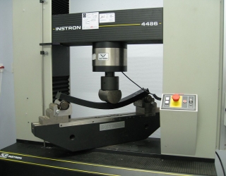
- Universal testing machine
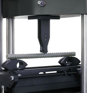
- Flexural fixture for three-point loading
- A slender rod (bending specimen). The rod material could be any engineering material such as steel, cast iron or concrete.
Procedure
- Mount the specimen on the three-point bending test fixture.
- Determine the maximum load and the number of loading increments, based on the maximum allowable stress, span length and transverse dimension of the specimen.
- Paste strain gauges and make connections to strain gauge instrumentation.
- Load the specimen based on the predetermined load increment. For each increment, record both the incremental load and the resultant strain.
- Analyze the relationship between the load increment and strain increment from the tabulated data set. Compare their proportionality with that predicted by the theory.
- Uninstall the experiment and restore the testing machine.
Quiz
- What fundamental hypotheses are implied during the derivation of the bending stress formulae?
- Is your experimental result consistent with the theoretical prediction? If not, what are the most possible influential factors in your opinion?
- Which cross section is optimal for applying strain gauges in a three-point bending test? Sketch the strain gauge distribution for such a cross section?
- With only one more strain gauge, where will you paste it in order to determine the Poisson’s ratio of the testing material?
- Is bending normal stress affected by the Young’s modulus of the testing material? What about the beam deflection?
- In the incremental scheme, the self weight of the beam is typically neglected. In your opinion, under what condition this approximation becomes reasonable?
- How to determine the neutral axis from the experimental data? For a rectangular beam, does the neutral axis pass through the centroid of that cross section?
Further Reading
- Bending: http://en.wikipedia.org/wiki/Bending
- Three Point Flexural Test: http://en.wikipedia.org/wiki/Three_point_flexural_test
- Flexural Strength: http://en.wikipedia.org/wiki/Flexural_strength
- Euler–Bernoulli Beam Theory: http://en.wikipedia.org/wiki/Euler%E2%80%93Bernoulli_beam_theory#Three-point_bending
- Strain Gauge: http://en.wikipedia.org/wiki/Strain_gauge
- Flexure Test at Instron: http://www.instron.in/wa/applications/test_types/flexure/default.aspx
- Flexure Test ASTM Standards: http://www.instron.in/wa/applications/test_types/flexure/standards.aspx
- Flexure Test Typical Configurations:
http://www.instron.in/wa/applications/test_types/flexure/configurations.aspx