Animated Experiment:

Introduction
Many products and components are subjected to torsional loads during their operation. Products such as switches, fasteners, and automotive steering columns are just a few devices subjected to such torsional stresses. By testing these products in torsion, manufacturers are able to simulate real life service conditions, check product quality, verify designs, and ensure proper manufacturing techniques.
A torsion test can be conducted on most materials to determine the torsional properties of the material. These properties include but are not limited to shear modulus, yield shear strength, ultimate shear strength, rupture shear stress, and shear ductility. While they are not the same, they are analogous to properties that can be determined during a tensile test. In fact, the “torque versus angle” diagram looks very similar to a “stress versus strain” curve that is generated by a tensile test.
Because the shear stress and shear strain are obtained directly in the torsion test, rather than tensile stress and tensile strain as in the tension test, many investigators actually prefer this test to the tension test. Since all deformation of ductile materials is by shear, the torsion test would seem to be the more fundamental of the two.
Principle
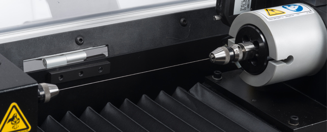
The torsion test is accomplished by simply clamping each end of a suitable specimen in a twisting machine that is able to measure the torque applied to the specimen. Care must be used in gripping the specimen to avoid any bending. A device called a troptometer is used to measure angular deformation. This device consists of two collars which are clamped to the specimen at the desired gauge length. One collar is equipped with a pointer the other with a graduated scale, so the relative twist between the gauge marks can be determined. The troptometer is useful for measuring strains up to and slightly past the elastic limit. For larger plastic strains, complete revolutions of the collars are counted.
The test, then, consists of measuring the angle of twist at selected increments of torque. Expressing the twist as the angular deflection per unit gauge length, one is able to plot a torque versus angle of twist per unit gauge length diagram that is analogous to the load deflection diagram obtained in the tension test. To be useful for engineering purposes, it is necessary to convert this torque-angle diagram to a shear stress versus shear strain diagram similar to the previous normal stress versus normal strain diagram. Recall that
the maximum shear stress = torque×shaft radius/polar moment of inertia
and
the maximum shear strain = shaft radius×total angle of twist\gauge length.
Objective
Study the linearly elastic behavior of metallic material under torsion and to determine the shear modulus of elasticity.
Observe the complete behavior of metallic materials under torsion and determine qualitatively the relationship between torsional load and angle of twist for a full range of strains until failure.
Determine whether the metallic materials fail in tension, compression, or shear when it is subjected to torsional loads.
Compare the shear stress versus shear strain curve with the normal stress versus normal strain curve from a tensile test of the same material and quantitatively determine the corresponding elastic, plastic and strength parameters (for a ductile metal).
Apparatus
- Torsional Tester
- Circular Torsional Specimen

Procedure
- Determine the gauge length, measure the diameter at about three places and take the average value of the test specimen. Calculate the polar moment of inertia and torsional section coefficient.
- Estimate the ultimate shear strength from the torsional section coefficient, determine roughly the maximum required torque, and number of loading increments.
- Choose right torsional tester or set the appropriate range by capacity change lever of a given tester.
- Mount the specimen in the fixture of the tester and initialize the load pointer and angular measurer.
- Draw a line down the length of the test section of the specimen with a chalk; this serves as a visual aid to the degree of twist being put on the specimen during torsional loading.
- Carry out straining by manually rotating the hand wheel in predetermined increments and take note of the torque and the corresponding angle of twist for each increment. - Electromechanical drive system can also be used if available.
- Plot a graph between torque and angle of twist and quantitatively determine the elastic, plastic and strength parameters, in analogy to those of a tensile test.
Quiz
- In a torsional test, do plane sections remain plane after twisting?
- Describe the distribution law of shear stress on a cross section?
- Is the shear strain a function of radius?
- Describe the failure mode of brittle and ductile shafts subjected to torsional loads?
- Why is the orientation of the rupture plane different for brittle and ductile shafts?
- How is the shear modulus related to Young’s modulus?
Further Reading
- Torsion Test at Instron: http://www.instron.in/wa/applications/test_types/torsion/default.aspx
- Torsional Test Basics at Instron: http://www.instron.in/wa/applications/test_types/torsion/basics.aspx
- Shear Stress: http://en.wikipedia.org/wiki/Shear_stress
- Shear Modulus: http://en.wikipedia.org/wiki/Shear_modulus
- Torsion Spring: http://en.wikipedia.org/wiki/Torsion_spring
- Torsion: http://en.wikipedia.org/wiki/Torsion_%28mechanics%29